
Bairon McAdams sits down with Dominic Jainy to unpack a quiet killer on certain RTX 3090 boards: shroud screws placed perilously close to live traces. We explore how pressure turns into shorts, why routine pad swaps go sideways, and the exact checks that catch trouble early. Dominic walks through a real save that needed three driver MOSFETs, a phase controller, and two trace repairs, then pulls the lens back to better design and owner-safe mitigations. The thread through it all: careful geometry, deliberate torque, and disciplined diagnostics prevent heartache.
Many RTX 3090 cards place shroud screws close to PCB traces. How does that geometry translate into real-world failures, what early warning signs should owners watch for (visual, thermal, electrical), and what diagnostics confirm risk before damage occurs?
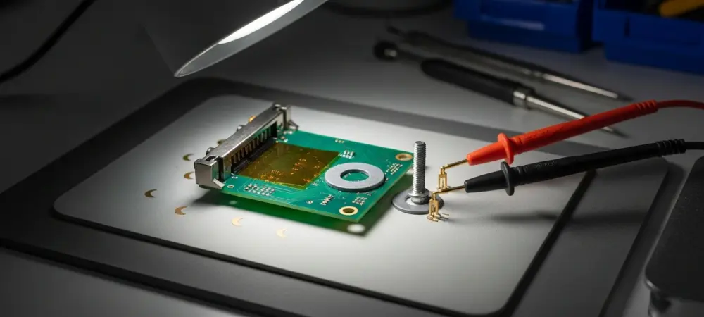
Two small side screws can funnel force straight into traces. That turns a minor over-tighten into a buried short or a clean trace cut. Watch for tiny crescent scuffs by the “GeForce RTX” shroud, or hot spots at idle. Confirm risk with continuity around those holes and quick resistance-to-ground checks on VRM rails.
Can you break down how overtightening a shroud screw breaches copper traces—typical torque ranges, stack-up tolerances, and failure modes—and what practical safeguards (washers, shorter screws, torque-limiting drivers) meaningfully lower the risk?
The screw tip becomes a punch when the stack-up is thin. It can dimple solder mask, then score copper, then split it. Nylon washers and slightly shorter screws blunt that punch. A torque-limiting driver set low finishes the job with feel, not force.
For someone replacing thermal pads, what precise steps prevent trace damage—measuring pad thickness, alignment checks, reassembly torque sequence, and inspection points—and what common mistakes push pressure paths into the PCB?
Measure old pads before removal and match thickness exactly. Dry-fit the shroud and sight the two side screws for clearance. Tighten in a cross pattern, a quarter turn at a time. The big mistake is chasing contact by cranking those two screws last.
After reassembly, what verification routine should be mandatory—resistance-to-ground checks on VRM rails, continuity around screw locations, staged power-up with a bench PSU—and how should anomalies be interpreted and escalated?
Log resistance-to-ground on core and memory rails before power. Probe continuity from pads near those screw holes to their next test point. If readings drop sharply, stop and re-open. Only then stage power with a current-limited bench PSU and monitor draw.
When the VRM is compromised, what symptoms typically appear—boot behavior, fan spin patterns, current draw, visual cues—and how do you triage between shorted drivers, controller failure, or trace cuts?
You’ll see fans twitch, then stall, or a dead card with brief pulse. Current can spike, then clamp, even at low set limits. Darkened lacquer or tiny crush marks near the shroud are tells. A hard short points to drivers; flat control lines hint controller; no continuity screams cut trace.
In a repair that required three driver MOSFETs and a phase controller, what was your end-to-end workflow—fault isolation, parts sourcing, rework technique, validation—and what success rates, costs, and turnaround times can owners realistically expect?
Isolation started with low-ohm hunting, then thermal and IPA tests. Three driver MOSFETs and a phase controller were replaced, plus two trace fixes. Parts were donor-pulled and reflowed with tight thermal shielding. Expect days, not hours, and success when all rails behave cold and hot.
How do you approach fixing cut PCB traces—micro-jumpers, enamel wire routing, UV mask reinforcement—and what are the long-term reliability and thermal considerations compared with intact factory traces?
I expose copper, stitch with a micro-jumper, and route enamel wire clean. UV mask locks it down and spreads stress. It runs a bit hotter than a broad copper plane. But done neatly, it’s solid for the long haul.
From a design standpoint, how should board partners rethink shroud-screw placement—clearance rules, screw length, insulating barriers—and what quick engineering changes could cut these failures without major retooling?
Pull those two screws back from any live run. Shorten the screws and add hard stops in the plastic. Drop a stiff polyimide shield over the zone. None of that needs a new PCB spin.
What owner-applied mitigations are both effective and low-risk—nylon washers, shorter screws, printed spacers—and how do you balance those against warranty concerns and serviceability?
Nylon washers and a half-turn shorter screw are easy wins. A thin printed spacer under the shroud tab works, too. Keep every original part in a bag for service. If in doubt, don’t break stickers; preserve warranty first.
If you were training a repair shop, what checklist would you enforce—torque chart, pad-thickness log, pre/post Ohm readings, staged power-up—and what metrics would you track to prove fewer returns and failures?
Log pad thicknesses and before/after Ohm numbers. Use a torque chart and mark each fastener as set. Power up in stages and record current profiles. Track comebacks and DOA rates to prove the process.
For hidden shorts that don’t show obvious damage, what’s your diagnostic stack—thermal camera, IPA evaporation tests, voltage injection, current-limited bench supply—and can you outline a step-by-step procedure with pass/fail criteria?
Start cold with resistance checks and mapping. Inject a low voltage with a current cap and watch thermal or IPA bloom. Local heat means a path; no heat means look upstream. Pass is stable draw and no hot spot; fail is fast bloom near those two screws.
Are similar screw-induced trace risks appearing on other GPUs or generations, and what patterns in shroud design or PCB layout should technicians research before opening a card?
Any card that tucks side screws near signal runs is suspect. Slim side shrouds with decorative plates are repeat offenders. Check for long screws near memory or VRM zones. If you see that pairing, proceed gently.
When a design quirk contributes to failure after standard maintenance, what documentation, photos, and measurements help owners seek fair support, and how have manufacturers typically responded in your experience?
Photograph the two screw sites before and after tear-down. Log resistance values and capture the repair area with macro shots. Note the replaced three driver MOSFETs and the phase controller, if done. Responses vary, but clean evidence boosts your odds.
Do you have any advice for our readers?
Respect those tiny screws like they’re chisels. Take photos, measure pads, and tighten by feel, not ego. If a reading feels off, stop and rethink. A calm quarter turn today can save three MOSFETs tomorrow.