

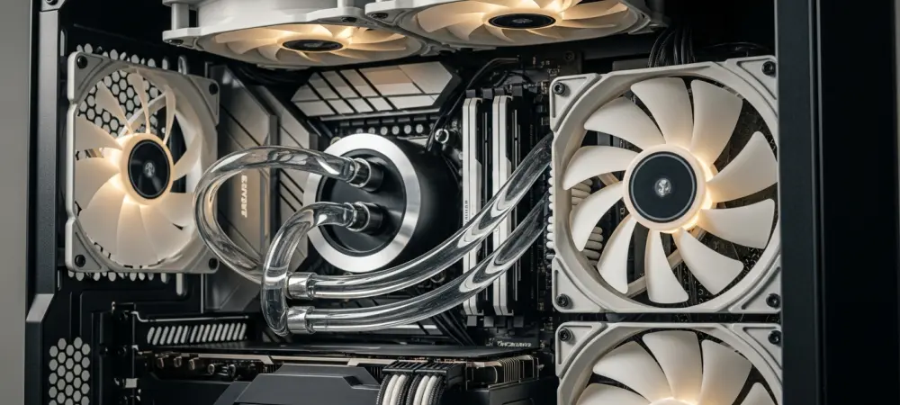
The modern motherboard has undergone a radical transformation from a simple substrate of copper traces into a highly sophisticated command center capable of managing the intricate thermal dynamics of high-performance silicon. As processors continue to push the boundaries of power density and clock speeds, the necessity for precise cooling control has never been more critical for system stability. While the casual observer might perceive fan headers as simple electrical outlets designed to spin plastic blades, these interfaces actually represent a complex marriage of electrical engineering and real-time data processing. Every pin on a standard header serves a dedicated purpose, facilitating a constant dialogue between the central processing unit and the cooling hardware to prevent catastrophic failure while maintaining acoustic comfort. This technological evolution reflects a broader trend in computing where even the most basic peripherals are now integrated into a holistic, software-defined ecosystem that prioritizes efficiency.
The Four-Pin Layout: Decoding Modern Engineering
The standard four-pin layout found on the CPU_FAN header is significantly more advanced than the antiquated two-pin or three-pin designs that dominated the market in previous decades. While the first two pins provide the necessary ground and a steady 12V power supply to the motor, the introduction of Pulse Width Modulation on the fourth pin fundamentally changed how cooling is managed. Instead of reducing the voltage to slow a fan down—a method known as DC regulation that can cause motors to stall or fail at low speeds—PWM sends a high-frequency signal that effectively toggles the power on and off thousands of times per second. This digital approach to speed control provides much higher precision and a wider range of operating revolutions than traditional analog methods ever could in the high-performance builds of 2026.
In addition to power delivery and control, the third pin serves as a vital communication link known as the tachometer, which enables the system to monitor the physical state of the cooling hardware. This pin sends a specific pulse signal back to the motherboard for every revolution of the fan, allowing the BIOS or the operating system to calculate the exact speed in revolutions per minute. This creates a continuous feedback loop that is essential for modern thermal management algorithms; as the processor experiences a sudden spike in workload and temperature, the motherboard detects the change and immediately instructs the fan to increase its velocity. By having an accurate real-time measurement of the fan performance, the system can verify that the cooling solution is responding correctly to the thermal load. If the reported speed drops below a certain threshold while temperatures are rising, the motherboard can take defensive actions to prevent damage to the delicate internal components.
Fail-Safe Protocols: Built-in Safety Features and Boot Logic
Modern motherboard manufacturers have integrated a critical fail-safe mechanism into the CPU_FAN header specifically designed to prevent the catastrophic hardware failure that once plagued early computers. In the past, a sudden fan failure could lead to a condition known as thermal runaway, where a processor would overheat so rapidly that the internal silicon would sustain permanent damage before the user even noticed a problem. To mitigate this risk, the system performs a thorough check during the Power-On Self-Test process every time the computer is turned on. If the motherboard does not detect a valid RPM signal coming from the CPU_FAN header during this initial sequence, it will often refuse to proceed with the boot process and display a prominent warning message. This design ensures that the machine never attempts to load a demanding operating system unless it can verify that a functional cooling device is actively protecting the most expensive component in the entire build.
While these safety protocols are essential for hardware protection, they can occasionally present challenges for enthusiasts using advanced cooling configurations or specialized external fan controllers. Many premium liquid cooling solutions and high-capacity fan hubs draw their primary electrical power directly from the power supply unit via SATA or Molex connectors rather than through the motherboard headers. Consequently, these devices may not transmit a tachometer signal back to the CPU_FAN header, leading the motherboard to erroneously conclude that no cooler is present and triggering a boot failure. To address this issue, builders must often navigate the BIOS settings to manually disable the fan speed monitoring feature or utilize a dedicated dummy signal wire that bridges the cooler and the motherboard. Understanding this logic is vital for troubleshooting modern systems, as it highlights the intentional friction between universal safety standards and the specialized requirements of custom hardware.
Specialized Programming: Functional Differences Between Fan and Pump Headers
Although the CPU_FAN and AIO_PUMP headers may appear identical to the naked eye, they are programmed with fundamentally different default behaviors that reflect their specific roles in the cooling system. A standard fan header is designed to be highly dynamic, utilizing sophisticated thermal curves to constantly adjust the fan speed based on the current temperature of the processor. This ensures that the computer remains quiet during light tasks while providing maximum airflow only when the workload demands it. In contrast, the AIO_PUMP header is typically configured by the manufacturer to operate at 100% output at all times without any modulation. This constant voltage is necessary because liquid cooling pumps are engineered to maintain a steady and consistent flow of coolant through the loop. Fluctuations in pump speed can lead to pockets of stagnant heat within the water block or unnecessary wear on the pump motor, which is often rated for a fixed duty cycle rather than variable speeds.
Plugging a standard case fan into an AIO_PUMP header without adjusting the settings can lead to a suboptimal user experience characterized by excessive noise and unnecessary power consumption. Because the pump header defaults to the maximum possible voltage, any fan connected to it will immediately ramp up to its highest rated speed the moment the system receives power. While most modern motherboards allow users to enter the BIOS and reconfigure a pump header to follow a custom fan curve, the default setting remains a high-performance profile suited for mechanical pumps. Furthermore, pump headers are often rated for higher amperage—sometimes up to 2 or 3 amps—to accommodate the significant electrical draw of powerful water pumps. Using the correct header ensures that the cooling components receive the appropriate electrical current and logic signals, allowing the entire system to operate as the manufacturer intended without the need for extensive manual recalibration or software interference.
Scalable Cooling: Optimizing Systems with Splitters and Hubs
For builders looking to maximize their cooling capacity by running multiple fans from a single header, the use of Y-splitters and powered hubs offers a scalable solution that maintains central control. When a builder utilizes a standard Y-splitter, the PWM control signal from the motherboard is shared across all connected fans, which causes them to increase and decrease their speed in perfect synchronization. However, a critical technical nuance involves the management of the tachometer signal; only one fan in the daisy-chain should be allowed to send its RPM data back to the motherboard. If multiple fans attempted to report their individual speeds simultaneously on the same pin, the resulting signal interference would lead to erratic readings and potentially disable the motherboard’s ability to monitor the cooling status. Most high-quality splitters are designed with this in mind, featuring one connector with four pins and the others with only three pins to ensure signal clarity for the controller.
Powered fan hubs represent an even more robust solution for complex builds by decoupling the control logic from the actual power delivery mechanism. These devices receive the PWM instruction signal from a motherboard header but draw the actual electrical current directly from the power supply unit via a dedicated power connector. This architecture is significantly safer for the motherboard, as it prevents the delicate internal traces from being overloaded by the combined power draw of several high-performance or high-static-pressure fans. By offloading the electrical load to the PSU, builders can safely manage upwards of ten fans from a single motherboard source without risking a short circuit or thermal damage to the board itself. Integrating these hubs into a system design allowed for cleaner cable management and more consistent performance across the entire chassis. This approach ensured that the thermal management system remained resilient even under the most demanding workloads.
The Evolution of Cooling: Advancements in Thermal Control Logic
The landscape of cooling technology transitioned toward a more integrated and automated approach where hardware and software became inseparable. Motherboard manufacturers recognized that static fan curves were no longer sufficient for the rapid thermal transients of modern multi-core processors. As a result, the logic within these headers was enhanced to incorporate machine learning algorithms that analyzed historical thermal data to predict temperature spikes before they occurred. This move away from reactive cooling toward proactive management allowed systems to maintain lower average temperatures with less acoustic variance. The development of more robust headers also accommodated the increasing power requirements of sophisticated custom loops, ensuring that the interface remained a reliable backbone for extreme overclocking. These innovations represented a significant leap forward in how enthusiasts managed the delicate balance between maximum performance and the physical limitations of their cooling hardware. To ensure the best results in any new build, it was highly recommended that users carefully audit the maximum amperage ratings of their specific motherboard headers before connecting multiple devices. Verifying whether a header was designated as a high-amperage port could prevent long-term degradation of the electrical components and ensure that pumps operated at their intended flow rates. Additionally, keeping the motherboard firmware updated became a crucial step, as manufacturers frequently released BIOS updates that refined fan control algorithms for newly released hardware. Looking toward future builds, the focus should remain on utilizing dedicated pump headers for liquid components while reserving the CPU_FAN header for primary air or liquid exhaust signals to maintain safety protocols. By adhering to these practices and leveraging the specialized capabilities of modern headers, builders maximized system stability and extended the lifespan of their high-end computing components.